Field Service and Troubleshooting
For AE Techron 7548 and 2110 Amplifiers
Remove and Replace the Amplifier Top Cover
Uninsulated terminals with AC mains potential are exposed when the top cover is removed. Do not proceed until AC Mains has been disconnected.
Do not attempt to remove the top cover while the amplifier is running. Turn the amplifier off and disconnect the AC Mains before removing the amplifier's top cover.
After turning the amplifier off, let the unit sit for 3-5 minutes before removing the top cover. This will allow the electrical charge in the power supply capacitors to discharge.
This document assumes competence on the part of the reader in terms of amplifier systems, electronic components, and good electronic safety and working practices.
Safety First
Throughout this document, special emphasis is placed on good safety practices. The safety graphics provided here are used to highlight certain topics which require extra precaution.
Summary
These instructions describe the process for removing and replacing the top cover of a 7548 or 2110 amplifier.
Tools Required
T-15 Torx driver
1/8-inch Hex Key driver
5/32-inch Hex Key driver
Procedure
- Remove power from the amplifier and disconnect any load from the amplifier outputs. Wait a minimum of three minutes to allow the amplifier's capacitors to discharge.
- Remove front panel:
- Use the 1/8-inch hex key driver to remove the four (4) button head hex screws from the front panel, as shown in Figure 1.
- Pull the panel towards you to remove.
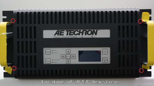
Figure 1: Front panel screw locations on 7548 amplifier
Procedure (cont.)
- Remove top cover:
- Use the T-15 Torx driver to remove four (4) Torx screws from each side of the unit.
- Use the T-15 Torx driver to remove six (6) Torx screws from the back of the unit.
- Use the 5/32-inch hex key driver to remove two (2) hex key screws from the front of the unit.
- Pull the cover straight up to remove.
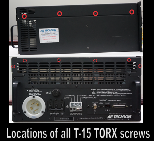
Figure 2: Top cover Torx screw locations on 7548 amplifier
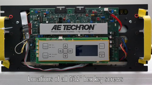
Figure 3: Top cover 5/32-inch hex key screw locations on 7548 amplifier
- To replace top cover:
- Replace cover onto amplifier.
- Insert and tighten the two (2) 5/32-inch key screws on the amplifier front (next to handles).
- Insert and tighten the four (4) T-15 Torx screws on each side of the amplifier.
- Insert and tighten the six (6) T-15 Torx screws on the back of the amplifier.
- Replace the front panel on the front of the amplifier.
- Insert and tighted the four (4) 1/8-inch button head hex screws.