4301 Series: Complete solution for DC voltage variations and transients testing

The 4301 Series Telecom Test Systems have been specially designed for EMC testing of network telecommunications equipment and are the best systems available for producing the waveforms required for transient voltage measurements as described in GR-1089 Section 10 and ATIS-0600315.2007.
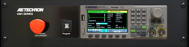
The 4301 includes a SDG2042X Function/Arbitrary Waveform Generator, which comes pre-programmed and integrated into
the 4301 system. Together, the 4301 with Siglent AWG provide a complete solution for GR-1089 Section 10/ATIS-0600315.2007 testing.
The 4301 system is available in four standard configurations and is capable of slew rates of up to 60 V/µsec. In its largest configuration (model 4301-240), the 4301 system can provide up to 240A of DC at ±50VDC and can provide pulses of up to 800 amps at voltages of up to ±100V. The system has a voltage gain of 20 and can accept input voltages of up to ±10V.
Lower power versions of the 4301 amplifier solution are available for users with lower current requirements: 4301-180 (180A), 4301-120 (120A) and 4301-60 (60A).
4301 Series
Telecom Test Systems
- Complete solution for GR-1089 Section 10 and ATIS-0600315.2007 DC Voltage Variations and Transients Testing
- Siglent SDG2042X Function/Arbitrary Waveform Generator comes pre-programmed and integrated into the 4301 system
- Four selectable compensation settings
Key Performance Capabilities:
- Slew rates up to 60 V/µsec.
- Up to 240A DC at +50VDC or –50VDC (4301-240 configuration).
- Can provide pulses of up to 800 amps at voltages of up to ±100V (4301-240 configuration).
- Adjustable compensation allows the system to maintain a 50V/2 µsec rise-time over a wide range of current outputs.
Models
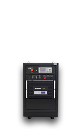
4301-60
Maximum Continuous DC Current (±50 VDC): 60A
Maximum Pulse DC Current (up to ±100 VDC): 200A
Voltage Gain: 20
Maximum Input Voltage: ±10V, unbalanced
Compensation Setting (for current required at system output),
Setting 0 (off): 0 to 6A;
Setting 1: 6 to 12A
Setting 2: 12 to 50A
Setting 3: 50 to 60A
Current Monitor Output: 20A output = 1V monitor output
Voltage Monitor Output: 20V output = 1V monitor output
Required AC Mains, three-phase, 47-60 Hz, five-conductor wiring (±10%),
208 VAC: 30A AC service;
400 VAC: 15A AC service
Dimensions (HxWxD): 27 x 34 x 22.5 in. (68.6 x 86.4 x 57.2 cm)
Net Weight: 307 lbs. (139 kg)
Shipping Weight: 458 lbs. (208 kg)
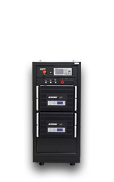
4301-120
Maximum Continuous DC Current (±50 VDC): 120A
Maximum Pulse DC Current (up to ±100 VDC): 400A
Voltage Gain: 20
Maximum Input Voltage: ±10V, unbalanced
Compensation Setting (for current required at system output),
Setting 0 (off): 0 to 12A;
Setting 1: 12 to 24A
Setting 2: 24 to 100A
Setting 3: 100 to 120A
Current Monitor Output: 40A output = 1V monitor output
Voltage Monitor Output: 10V output = 1V monitor output
Required AC Mains, three-phase, 47-60 Hz, five-conductor wiring (±10%),
208 VAC: 60A AC service;
400 VAC: 30A AC service
Dimensions (HxWxD): 52 x 22 x 31.5 in. (132 x 55.9 x 80 cm)
Net Weight: 454 lbs. (206 kg)
Shipping Weight: 589 lbs. (267 kg)
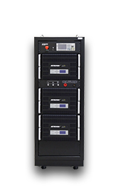
4301-180
Maximum Continuous DC Current (±50 VDC): 180A
Maximum Pulse DC Current (up to ±100 VDC): 600A
Voltage Gain: 20
Maximum Input Voltage: ±10V, unbalanced
Compensation Setting (for current required at system output),
Setting 0 (off): 0 to 18A;
Setting 1: 18 to 36A
Setting 2: 36 to 150A
Setting 3: 150 to 180A
Current Monitor Output: 60A output = 1V monitor output
Voltage Monitor Output: 10V output = 1V monitor output
Required AC Mains, three-phase, 47-60 Hz, five-conductor wiring (±10%),
208 VAC: 90A AC service;
400 VAC: 45A AC service
Dimensions (HxWxD): 74 x 22 x 31.5 in. (188 x 55.9 x 80 cm)
Net Weight: 697 lbs. (316 kg)
Shipping Weight: 897 lbs. (407 kg)
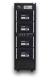
4301-240
Maximum Continuous DC Current (±50 VDC): 240A
Maximum Pulse DC Current (up to ±100 VDC): 800A
Voltage Gain: 20
Maximum Input Voltage: ±10V, unbalanced
Compensation Setting (for current required at system output),
Setting 0 (off): 0 to 24A;
Setting 1: 24 to 50A
Setting 2: 50 to 200A
Setting 3: 200 to 240A
Current Monitor Output: 80A output = 1V monitor output
Voltage Monitor Output: 10V output = 1V monitor output
Required AC Mains, three-phase, 47-60 Hz, five-conductor wiring (±10%),
208 VAC: 120A AC service;
400 VAC: 60A AC service
Dimensions (HxWxD): 74 x 22 x 31.5 in. (188 x 55.9 x 80 cm)
Net Weight: 850 lbs. (386 kg)
Shipping Weight: 1050 lbs. (476 kg)
Common Data (all models)
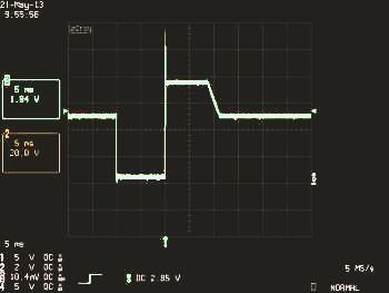
4301 System Combined Waveform Output
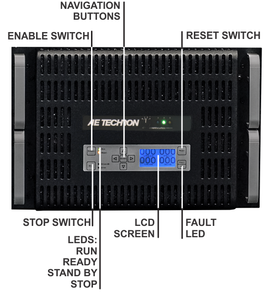
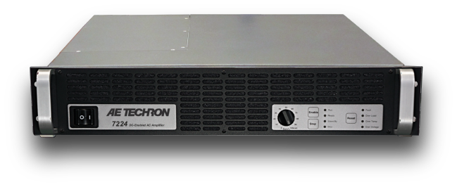
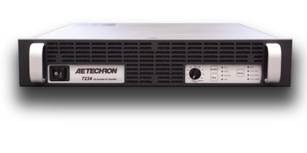
Indicators and Controls
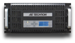
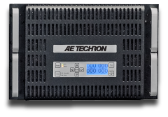
Theunit's indicators and controls are located on the 4301 amplifier modules. The 4301 models contain between one and four amplifier modules.
LED Displays: Indicators for Run, Ready, Standby, and Stop status, and Fault conditions in the output stage.
LCD Display:Can be user-configured for up to four simultaneous displays reporting one, two, or all four of the following: Voltage Peak, Voltage RMS, Current Peak and Current RMS. When the amplifier module is in a Fault condition, the LCD Display lists the type of fault condition and gives suggested corrective action.
Navigation Buttons:The Navigation Buttons provide four arrow keys to allow navigation through the various LCD display options.
Soft Touch Switches: Soft touch switches allow the selection of Run (Enable), Stop and Reset functions.
Compensation Setting: A four-position rotary control allows the selection of optimum compensation settings according to the total current required at the system output.
Compensation LEDs: When the amplifier module is receiving AC power, the colored LED associated with the selected Compensation setting will be lit.
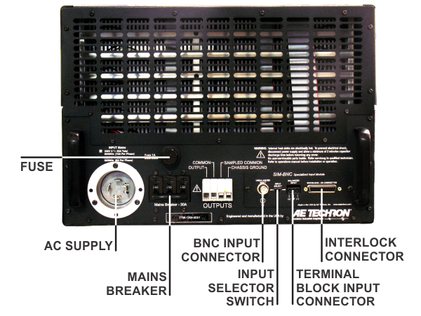
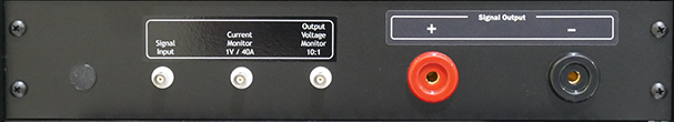
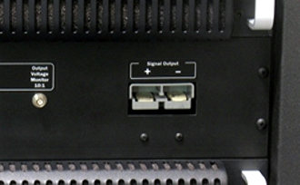
Inputs and Outputs
The unit's inputs and outputs are located on the cabinet's front panel.
Signal Input: A BNC connector accepts input from an arbitrary waveform generator.
External Trigger Output: A BNC connector provides the signal to the Trigger In connector on the AWG.
Current Monitor Output: A BNC connector provides scaled voltage output for current monitoring.
Voltage Monitor Output: A BNC connector provides scaled voltage output for voltage monitoring.
Signal Output: 250A Pin Plug connectors (or optional Anderson SB350 connectors) provide signal output to the equipment under test.
AWG: A Siglent SDG2042X Function/Arbitrary Waveform Generator is integrated into the 4301 system. The AWG comes pre-programmed with the required test waveforms and is mounted securely within the 4301 cabinet. A GPIB port located next to the AWG on the system front panel allows communication with the AWG through a user-supplied computer.
Options
SB350 Outputs Option: Anderson SB350 output connectors can be substituted for the standard 250A Pin Plug connectors.
Protection
Fault: The Fault LED on an amplifier module will light and the error message "Warning! Output Device Fault" will be displayed on the LCD screen if the module’s output stage stops operating. If this happens, contact AE TECHRON for servicing information.
AC Under/Over Voltage Protection: If the AC line voltage rises or drops more than10% of the nominal operating voltage, the system will be forced to Standby and the error message "Warning! Overvoltage" will be displayed on the LCD screen of the amplifier module(s).
Over Current: Each amplifier module contains breaker protection on both the unit’s main power supply and the low-voltage supplies. The 4301 system provides a Main Power breaker switch and an Auxiliary Power breaker switch located inside the cabinet rear door.
Over Temperature: Each amplifier module contains separate output transistor, heat-sink and transformer temperature monitoring and protection circuits.
Physical Characteristics
Cabinet: Welded steel cabinet with a textured black, powder-coat finish.
Main Power: A main power selector located on the system front panel controls the main power supply to the system.
Operating Temperature: 10°C to 50°C (50°F to 122°F), Maximum Output Power de-rated above 30°C (86°F).)
Humidity: 70% or less, non-condensing.
Cooling: The 4301 system amplifier modules employ forced air-cooling from front to back through removable filters via six 100 ft3/min. fans per unit. No space is required between rack-mounted modules. Provide room at the cabinet back to allow for proper airflow.
Amplifier Module Front & Back
Cabinet Panels
Options
Optional SB350 Output Connectors
The 4301 can be ordered with optional Anderson SB350 output connectors to be used instead of the standard 250A Pin Plug connectors..
Downloads
You might also be interested in:
Recommended Products
Want to discuss a product or application?
Our knowledgeable sales and support staff can help find the right system for your needs.
We're the audio-bandwidth experts.